How to install your sliding wardrobe doors
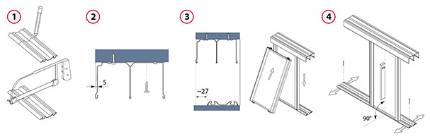
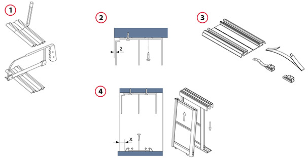
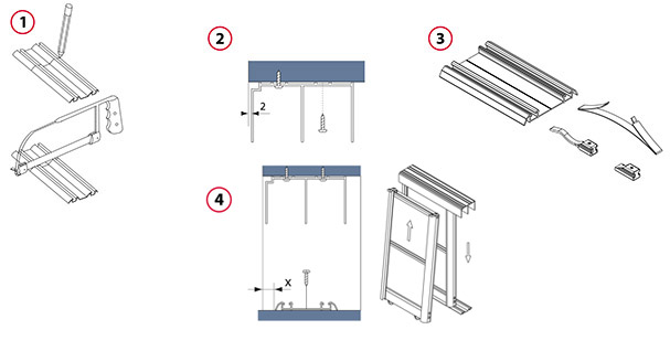
1. Cut the tracks
Carefully measure the width of the opening at top and bottom, and reduce the lengths measured by about 2-3 mm. Measure off the required track length, marking the future cut line on the tracks. Use a fine-toothed metal cutting saw to cut off the redundant part of the tracks.
Advice:The tracks to be installed should be about 50 mm longer than the opening width. This spare length will make it possible to avoid measurement errors and it is easy to trim. Take care not to damage the track surface while cutting. In order to facilitate top track cutting, insert 38 mm thick wood blocks or a reversed piece of track into the track. This will prevent track deflection during the cutting process.
2. Install the top track
Fix the top track with screws, offsetting its flat surface by 5 mm from the door face (inwards). Install the top track with the shade line facing forward in order to mask ceiling irregularities. If a multiple-track system is installed, fix the other tracks so that they fit tightly against each other along the entire length.
Advice: Before you start installation use a detector to make sure there is no electrical wiring at the screw fixing points. Avoid applying excessive force when tightening screws to prevent track deformation. Use flat-head screws for best results. The surface to which the track is fixed must not be curved.
3. Install the door
Lay the bottom track on the floor, offsetting it about 27 mm from the door face (inwards). Use a Philips screwdriver and the adjusting bolt to move bottom rollers out about 10 mm. Fully insert the door leaf in the top track, taking care not to damage the bottom rollers, then align the bottom end of the door leaf with the bottom track and slowly lower the leaf, letting the rollers snap into the track guides.
Advice: Before you install the doors, put a cardboard sheet on the bottom track to prevent damage to track surface. When the doors are already in position, remove the protective cardboard.
4. Install the bottom track
Use a level to make sure the door is exactly plumb; move the bottom track as necessary. Check if the door travels smoothly along the entire width of the opening. Having precisely set the bottom track, fasten it to the floor. Having installed the track, put the other door leaves in their respective tracks.
Advice: Before you fix the bottom track, make sure that it is positioned exactly parallel to the top track. With soft floor covering, before you fix the bottom track, cut out a strip of about 55 mm in width and replace it with a 55 mm timber batten. Alternatively, put a 100 mm floor batten between the floor covering and the bottom track. Avoid applying excessive force when tightening screws to prevent track deformation. Use flat -head screws for best results.
5. Adjust door position
Adjust door position by means of a Philips screwdriver and the adjusting bolts in the bottom rollers so that the doors fit tightly against the wall along the entire length. Door-to-floor clearance is adjustable between 10 and 40 mm (2 to 32 mm from the bottom track).
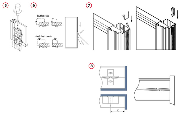
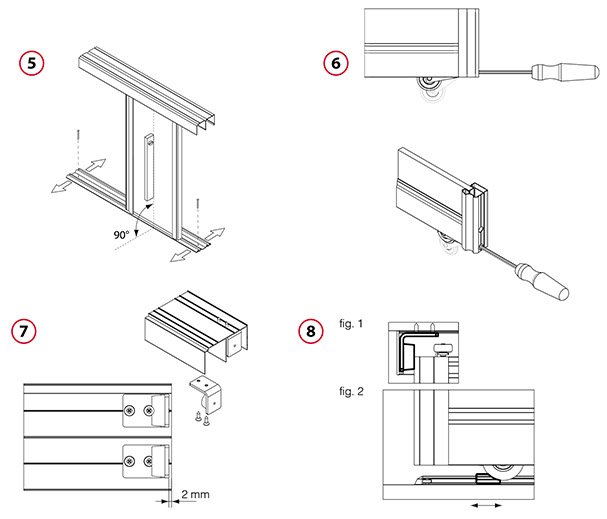
6. Fix the buffer and dust-stop brush strips
Having installed the doors, remove protective backing from the door profiles. With the backing removed, you can fix the buffer strips and the dust-stop brush strips. To ensure good adhesion of the brush strips to the profiles, gently clean the profiles with alcohol or white spirit. Fix the strips, working from top to bottom. Cut off excess strip.
7. Fix the buffer strip clip
To fix the clip 099249 or 099249A, the door must first be installed and adjusted. After that operation, fix the buffer strip and then mount the clip. For easier and correct installation, we recommend that the door should be taken off the tracks.
Advice: For details of the buffer strip clip installation see separate instructions, “Technical information– fixing the buffer strip clip” available on our website in the section designated for Authorised Partners.
8. Fix the buffer strip clip
Fix the positioner 099265 to the top track so that it fits against the middle part of the track at an appropriate distance from the wall. Cut the positioner 099259PLS to the right size and fix in the middle of the top track so that the door abuts on the side wall of the unit when closed.
For the Montreal profile
x = 32 mm, where no buffer strip is used,
x = 37 mm, where a buffer strip is used.
For the Halifax profile
x = 32 mm, where no buffer strip is used,
x = 37 mm, where a buffer strip is used.
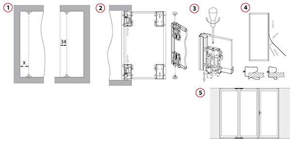
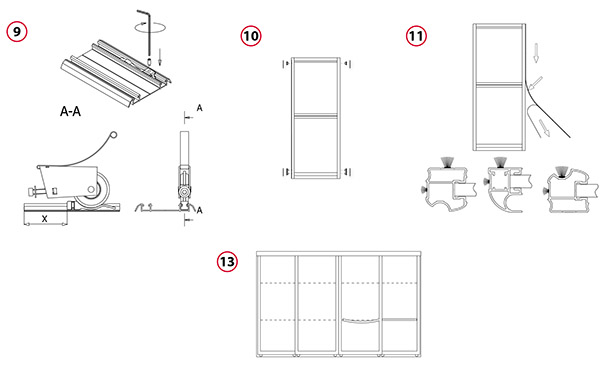
1. Install pivot pins
Set and fix the top and bottom pivot pins, offsetting them 34 mm inwards from the door face and at the following distance from the side wall:
x = 55 mm for the Halifax profile
x = 48mm for the Concord profile
x = 43 mm for the Montreal profile
Note: When fixing the pivot <?>base, use screws with a head diameter of not more than 8 mm.
2. Set the door in place
Use a Philips screwdriver and the adjusting bolts to insert the pivot socket slides in the connectors about 20 mm. Move the sockets outwards and fasten the socket fixing screw. Put the door upright so that the connectors with pivot sockets are aligned with the axis of the fixed pivot pins. The door should be in an open position. While turning the adjusting bolt, slip the bottom pivot socket slide out so that the socket is aligned with the pin and the door lifts slightly. Then slip out the top sliding pivot socket so that it is aligned with the pin, allowing for minimal play.
Advice: Exercise special care when installing doors. This operation should be performed by two persons.
3. Adjust the door
Using a Philips screwdriver and adjusting bolts in the top and bottom <?>connectors, adjust the door height. The door-to-floor/ceiling distance is adjustable between 3 and 20 mm.
4. Fix the buffer strips
Having installed the doors, remove safety backing from the door profiles. With the backing removed, you can fix the buffer strips. To ensure good adhesion of the strips to the profiles, gently clean the profiles with alcohol or white spirit. Fix the strips, working your way from top to bottom. Cut off excess strip.
Advice: Owing to a large gap between the wall and door, it is recommended that you use a dust stop brush strip instead of a buffer strip.
5. Fix the buffer strip clip
To fix the clip 099249 or 099249A, the door must first be installed and adjusted. After that operation, fix the buffer strip and then mount the clip. For easier and correct installation, we recommend that the door should be taken off the tracks.
Advice: For details of the buffer strip clip installation see separate instructions, “Technical information– fixing the buffer strip clip” available on our website in the section designated for Authorised Partners.
6. Fix the magnetic latch
Having adjusted the door, close it, place the magnetic latch at the door leaf, mark the position and open the door. Fix the magnetic latch to the floor/ceiling/wall.
Note: The latch keeps the door in a stable position when closed.
1. Cut the tracks
Carefully measure the width of the opening at top and bottom, and reduce the lengths measured by about 2-3 mm. Measure off the required track length, marking the future cut line on the tracks. Use a fine-toothed metal cutting saw to cut off the redundant part of the tracks.
Advice: The tracks to be installed should be about 50 mm longer than the opening width. This spare length will make it possible to avoid measurement errors and it is easy to trim. In order to facilitate top track cutting, insert 38 mm thick wood blocks or a reversed piece of track into the track. This will prevent track deflection during the cutting process.
2. Install the top track
Fix the top track with screws, offsetting its flat surface by 2 mm from the door face (inwards). Install the top track with the shade line facing forward in order to mask ceiling irregularities. If a multiple-track system is installed, fix the other tracks so that they fit tightly against each other along the entire length.
Advice: Avoid applying excessive force when tightening screws to prevent track deformation. Use flat-head screws for best results. The surface to which the track is fixed must not be curved.
3. Fix stoppers and positioners in the bottom track
If the track is to be fitted with bottom positioners and stoppers, slip them into the respective tracks before fixing. Fully in-sert the door leaf in the top track, taking care not to damage the bottom rollers, then align the bottom end of the door leaf with the bottom track and slowly lower the leaf, letting the rollers snap into the tracks.
For door weights under 12 kg use positioner 099259A.
For door weights between 12 kg and 25 kg use positioner 099259.
For door weights between 25 kg and 50 kg use positioner 099259B.
4. Install the door
Lay the bottom track on the floor, offsetting it from the door face (inwards) by about:
x = 11mm – Calgary Victoria Edmonton Hudson Quebec, profile
x = 18mm – Niagara Windsor profile
If the track is to be fitted with bottom positioners, slip them into the respective tracks before fixing. Fully insert the door leaf in the top track, taking care not to damage the bottom rollers, then align the bottom end of the door leaf with the bottom track and slowly lower the leaf, letting the rollers snap into the tracks.
Advice: Before you install the doors, put a cardboard sheet on the bottom track to prevent damage to track surface. When the doors are alrea-dy in position, remove the protective cardboard.
5. Install the bottom track
Use a level to make sure the door is exactly plumb; move the bottom track as necessary. Check if the door travels smoothly along the entire width of the opening. Having precisely adjusted the door position, install the other door leaves in their respective tracks.
Advice: Before you fix the bottom track, make sure that it is positioned exactly parallel to the top track. With soft floor covering, be-fore you fix the bottom track, cut out a strip of about 55 mm in width and replace it with a 55 mm timber batten. Alternatively, put a 100 mm floor batten between the floor covering and the bottom track. Avoid applying excessive force when tightening screws to prevent track deformation. Use flat-head screws for best results.
6. Adjust door position
Adjust door position by means of the adjusting bolts in the bottom rollers so that the doors fit tightly against the wall along the entire length. Door-to-floor clearance is adjustable between 11 and 20 mm (3 to 12 mm from the bottom track).
7. Fix the top track stopper
Before fixing the stopper, drill through-holes with a 4 mm drill bit. Then fix the stopper to the ceiling (upper wall) using screws suitable for the ceiling/wall material. If you install an end cap in the top track, insert the cap tabs between the track and the ceiling before finally fastening the stopper screws.
8. Adjust the bottom stopper and top stopper
Having installed the top track stopper, adjust the position of the stopper 099275 set in the bottom track. To do this, slide the door to the top stopper as shown in Fig. 1 and push the bottom stopper to the wheel edge (Fig. 2). Fasten the bottom stopper screw with a 1.5 mm Allen key to prevent its dislocation when the door is used.
9. Fix the positioner/stopper
Insert the positioner/stopper into the bottom track before is installation. After the bottom track is fixed to the floor, tighten the positioner with an M3x8 ISO 4026 set screw (the key and the screw are delivered in the kit). Remount the door and in-stall it in the right position. The distance between the positioner and the end of the track “X” depends on the stile (vertical profile) used. This way you can easily verify if the positioner is fixed properly and in which direction it should be moved if needed.
The positioner can be used in all bottom tracks:
– single 153000xx,
– double 153250xx,
– wide recessed single track 153260xx,
– narrow recessed single track 153255xx.
10. Fix the caps
Having installed and adjusted the door leaves, cover all installation holes by inserting the plugs 16000080 or by sticking the caps 16000090 or 16000085.
11. Fix the dust-stop brush strips and buffer strips
To ensure good adhesion of the strips to the profiles, gently clean the profiles with alcohol or white spirit. Fix the strips, working your way from top to bottom. Cut off excess strip.
Advice: for Niagara Windsor profiles, use a shorter 8mm strip 81100019. For other profiles, use a longer 12mm strip 81100020.
12. Fix the buffer strip clip
To fix the clip 099249 or 099249A, the door must first be installed and adjusted. After that operation, fix the buffer strip and then mount the clip. For easier and correct installation, we recommend that the door should be taken off the tracks.
Advice: For details of the buffer strip clip installation see separate instructions, “Technical information– fixing the buffer strip clip” available on our website in the section designated for Authorised Partners.
13. Fix the decorative strips
Having adjusted the door leaf height, mark the levels where decorative strips are to be fixed to the door leaves. For each leaf, carefully measure the distance between the stiles. Then cut the decorative strips to the required lengths and fix do-uble-sided self-adhesive tape 16000005 (0.8 mm thick) to the strips. Remove the protective tape and, bending the strip slightly, put it between the stiles and press against the panel.
14. Fix the decorative profile designed for the Hudson profile
The bottom track fascia 156220xx can be used as a decorative profile. For this purpose, fix double-sided self-adhesive tape 16000005 to the profiled indent and then stick the profile to the door leaf.
15. Install the locks
Fix the lock cylinder to the body with 3.9 x 16 screws 87000012. Fix the body with the attached cylinder to the stile on the outer door leaf with 3.9 x 16 self-tapping screws 87000055. Putting the door leaf in closed position, mark the outline of the lock body on the inner door. Then fix the lock base at the marked location on the board panel with 3.9 x 22 self-tapping screws 87000060, using two previously drilled holes.
For a mirror, fix the lock base using double-sided self-adhesive tape 16000005.
16. Adjust the bottom positioners
Put the door in set positions. Mark the positions of the bottom roller wheels. Slide the door to the side, press the positioner tips in place, and move the door to the desired position.
Advice: For light (narrow) doors use a single bottom positioner for each leaf; for heavy (wide) doors use two positioners per leaf.
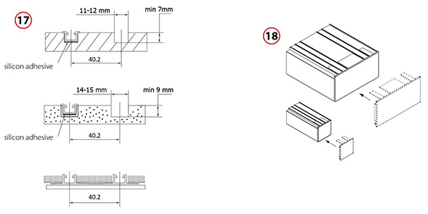
17. Fix the recessed bottom tracks
Recessed track
The recessed bottom track can be fixed in ceramic or parquet flooring or to furniture board. Leave or make a groove of 11- 12 mm in width and min. 7 mm in depth. Fix the track using silicon adhesive. Prior to fixing the track, apply an appropriate quantity of the adhesive along the bottom of the groove. Where two or more tracks are installed, provide for 40.2 mm spacing on centres (distance between track centre lines).
Track recessed into ceramic flooring:
A recessed bottom track can be mounted in ceramic flooring. Leave a groove of 14-15 mm in width and at least 9 mm in depth, in which to install the mounting profile 156250SU or embed it in mortar before it sets. Prior to door installation, fix the track 153255xx using silicone adhesive.
Wide recessed track:
The wide recessed track can be installed under carpeting. Fix the track using screws, double-sided self-adhesive tape or si-licon adhesive. Where two tracks are installed, correct spacing of tracks will be obtained by laying them next to each other so that the wider sides of their bases abut.
Advice: In an uneven floor, fix the tracks with silicon adhesive.
18. Fix the single or double top track end cap
Single and double top tracks can be fitted with end caps if the tracks are shorter than the width of the opening or they are installed outside the opening fitted with sliding doors. Before finally fastening the track fixing screws, insert the cap tabs between the track and the ceiling. Then fasten the track fixing screws.
19. Fix the single or double bottom track end cap
Insert the cap into the single or double bottom track. Having done this, fasten the cap with a 1.5 mm Allen key.
20. Mount the fascia
Install the bottom track fascia 156220xx, resting the special indent in the fascia on the bottom track rib. Then press the fascia until it snaps into place.
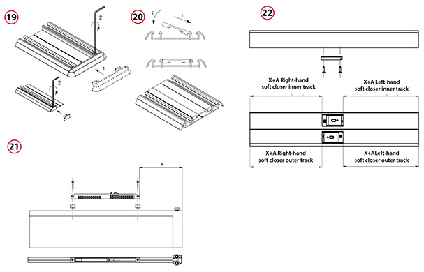
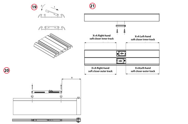
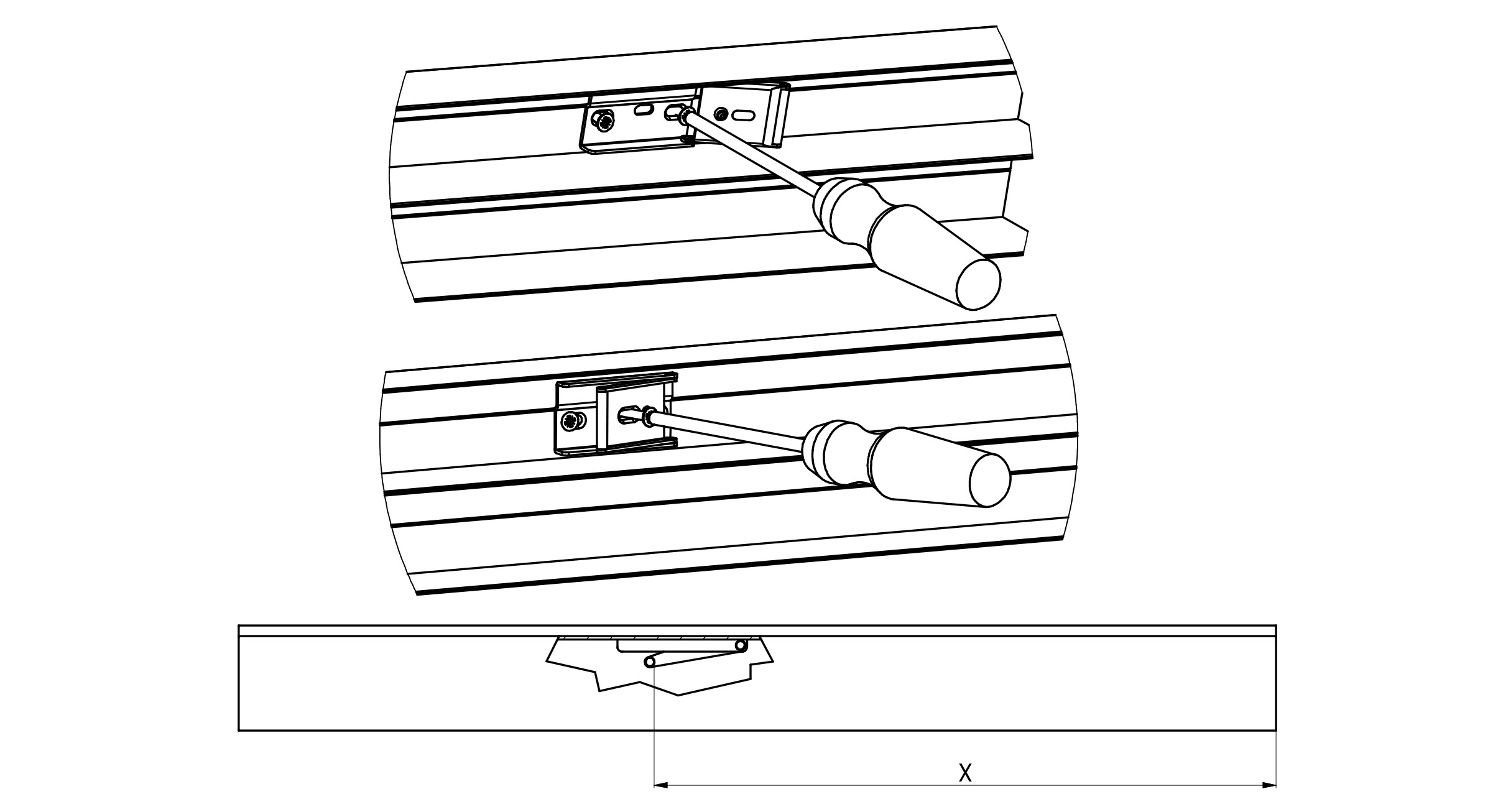
21. Mount the universal soft closer.
Fasten the universal soft closer 09923X to the narrow rail with adapters and 3.5 x 23 screws (aluminium system soft closer accessories). Having fastened the soft closer, measure the distance between the door edge and the soft closer (“X”).
22. Mount the soft closer trigger
Mount the trigger at the distance “X” + “A” from the track edge, fixing it to the top track with 3.5 x 16 screws.
For the right-hand soft closer in the outer track, dimension “A” = 55mm.
For the right-hand soft closer in the inner track, dimension “A” = 80mm.
For the left-hand soft closer in the outer track, dimension “A” = 80mm.
For the left-hand soft closer in the inner track, dimension “A” = 55mm.
Before fixing the screws, drill lead holes in the top track with a 2mm drill bit.
1. Cut the tracks
Carefully measure the width of the opening at top and bottom, and reduce the lengths measured by about 2-3 mm. Measure off the required track length, marking the future cut line on the tracks. Use a fine-toothed metal cutting saw to cut off the redundant part of the tracks.
Advice: The tracks to be installed should be about 50 mm longer than the opening width. This spare length will make it possible to avoid measurement errors and it is easy to trim. In order to facilitate top track cutting, insert 38 mm thick wood blocks or a reversed piece of track into the track. This will prevent track deflection during the cutting process.
2. Install the top track
Fix the top track with screws, offsetting its flat surface by 2 mm from the door face (inwards). Install the top track with the shade line facing forward in order to mask ceiling irregularities. If a multiple-track system is installed, fix the other tracks so that they fit tightly against each other along the entire length.
Advice: Avoid applying excessive force when tightening screws to prevent track deformation. Use flat-head screws for best results. The surface to which the track is fixed must not be curved.
3. Fix stoppers and positioners in the bottom track
If the track is to be fitted with bottom positioners and stoppers, slip them into the respective tracks before fixing. Fully in-sert the door leaf in the top track, taking care not to damage the bottom rollers, then align the bottom end of the door leaf with the bottom track and slowly lower the leaf, letting the rollers snap into the tracks.
For door weights under 12 kg use positioner 099259A.
For door weights between 12 kg and 25 kg use positioner 099259.
For door weights between 25 kg and 50 kg use positioner 099259B.
4. Set the door in place
Lay the bottom track on the floor, offsetting it from the door face (inwards) by about:
x = 11mm – for the Athabasca profile.
If the track is to be fitted with bottom positioners, slip them into the respective tracks before fixing. Fully insert the door leaf in the top track, taking care not to damage the bottom rollers, then align the bottom end of the door leaf with the bottom track and slowly lower the leaf, letting the rollers snap into the tracks.
Advice: Before you set the door in place, put a cardboard sheet on the bottom track to prevent damage to track surface. When the door is alrea-dy in position, remove the protective cardboard.
5. Install the bottom track
Use a level to make sure the door is exactly plumb; move the bottom track as necessary. Check if the door travels smoothly along the entire width of the opening. Having precisely adjusted the door position, install the other door leaves in their respective tracks.
Advice: Before you fix the bottom track, make sure that it is positioned exactly parallel to the top track. With soft floor covering, be-fore you fix the bottom track, cut out a strip of about 55 mm in width and replace it with a 55 mm timber batten. Alternatively, put a 100 mm floor batten between the floor covering and the bottom track. Avoid applying excessive force when tightening screws to prevent track deformation. Use flat-head screws for best results.
6. Adjust door position
Adjust door position by means of the adjusting bolts in the bottom rollers so that the doors fit tightly against the wall along the entire length. Door-to-floor clearance is adjustable between 11 and 20 mm (3 to 12 mm from the bottom track).
7. Fix the top track stopper
Before fixing the stopper, drill through-holes with a 4 mm drill bit. Then fix the stopper to the ceiling (upper wall) using screws suitable for the ceiling/wall material. If you install an end cap in the top track, insert the cap tabs between the track and the ceiling before finally fastening the stopper screws.
8. Adjust the bottom stopper and top stopper
Having installed the top track stopper, adjust the position of the stopper 099275 set in the bottom track. To do this, slide the door to the top stopper as shown in Fig. 1 and push the bottom stopper to the wheel edge (Fig. 2). Fasten the bottom stopper screw with a 1.5 mm Allen key to prevent its dislocation when the door is used.
9. Fix the positioner/stopper
Insert the positioner/stopper into the bottom track before is installation. After the bottom track is fixed to the floor, tighten the positioner with an M3x8 ISO 4026 set screw (the key and the screw are delivered in the kit). Remount the door and in-stall it in the right position. The distance between the positioner and the end of the track “X” depends on the stile (vertical profile) used. This way you can easily verify if the positioner is fixed properly and in which direction it should be moved if needed.
The positioner can be used in all bottom tracks:
– single 153000xx,
– double 153250xx,
– wide recessed single track 153260xx,
– narrow recessed single track 153255xx.
10. Fix the caps
Having installed and adjusted the door leaves, cover all installation holes by inserting the plugs 16000080 or by sticking the caps 16000090 or 16000085.
11. Fix the dust-stop brush strips and buffer strips
To ensure good adhesion of the strips to the profiles, gently clean the profiles with alcohol or white spirit. Fix the strips, working your way from top to bottom. Cut off excess strip.
Advice: for Niagara Windsor profiles, use a shorter 8mm strip 81100019. For other profiles, use a longer 12mm strip 81100020.
12. Fix the buffer strip clip
To fix the clip 099249 or 099249A, the door must first be installed and adjusted. After that operation, fix the buffer strip and then mount the clip. For easier and correct installation, we recommend that the door should be taken off the tracks.
Advice: For details of the buffer strip clip installation see separate instructions, “Technical information– fixing the buffer strip clip” available on our website in the section designated for Authorised Partners.
13. Fix the decorative strips
Having adjusted the door leaf height, mark the levels where decorative strips are to be fixed to the door leaves. For each leaf, carefully measure the distance between the stiles. Then cut the decorative strips to the required lengths and fix do-uble-sided self-adhesive tape 16000005 (0.8 mm thick) to the strips. Remove the protective tape and, bending the strip slightly, put it between the stiles and press against the panel.
14. Fix the decorative profile designed for the Hudson profile
The bottom track fascia 156220xx can be used as a decorative profile. For this purpose, fix double-sided self-adhesive tape 16000005 to the profiled indent and then stick the profile to the door leaf.
15. Install the locks
Fix the lock cylinder to the body with 3.9 x 16 screws 87000012. Fix the body with the attached cylinder to the stile on the outer door leaf with 3.9 x 16 self-tapping screws 87000055. Putting the door leaf in closed position, mark the outline of the lock body on the inner door. Then fix the lock base at the marked location on the board panel with 3.9 x 22 self-tapping screws 87000060, using two previously drilled holes.
For a mirror, fix the lock base using double-sided self-adhesive tape 16000005.
16. Adjust the bottom positioners
Put the door in set positions. Mark the positions of the bottom roller wheels. Slide the door to the side, press the positioner tips in place, and move the door to the desired position.
Advice: For light (narrow) doors use a single bottom positioner for each leaf; for heavy (wide) doors use two positioners per leaf.
17. Fix the recessed bottom tracks
Recessed track
The recessed bottom track can be fixed in ceramic or parquet flooring or to furniture board. Leave or make a groove of 11- 12 mm in width and min. 7 mm in depth. Fix the track using silicon adhesive. Prior to fixing the track, apply an appropriate quantity of the adhesive along the bottom of the groove. Where two or more tracks are installed, provide for 40.2 mm spacing on centres (distance between track centre lines).
Track recessed into ceramic flooring:
A recessed bottom track can be mounted in ceramic flooring. Leave a groove of 14-15 mm in width and at least 9 mm in depth, in which to install the mounting profile 156250SU or embed it in mortar before it sets. Prior to door installation, fix the track 153255xx using silicone adhesive.
Wide recessed track:
The wide recessed track can be installed under carpeting. Fix the track using screws, double-sided self-adhesive tape or si-licon adhesive. Where two tracks are installed, correct spacing of tracks will be obtained by laying them next to each other so that the wider sides of their bases abut.
Advice: In an uneven floor, fix the tracks with silicon adhesive.
18. Fix the single or double top track end cap
Single and double top tracks can be fitted with end caps if the tracks are shorter than the width of the opening or they are installed outside the opening fitted with sliding doors. Before finally fastening the track fixing screws, insert the cap tabs between the track and the ceiling. Then fasten the track fixing screws.
19. Mount the fascia
Install the bottom track fascia 156220xx, resting the special indent in the fascia on the bottom track rib. Then press the fascia until it snaps into place.
20. Mount the universal soft closer.
Fasten the universal soft closer 09923X to the narrow rail with adapters and 3.5 x 23 screws (aluminium system soft closer accessories). Having fastened the soft closer, measure the distance between the door edge and the soft closer (“X”).
21. Mount the soft closer trigger
Mount the trigger at the distance “X” + “A” from the track edge, fixing it to the top track with 3.5 x 16 screws.
For the right-hand soft closer in the outer track, dimension “A” = 55mm.
For the right-hand soft closer in the inner track, dimension “A” = 80mm.
For the left-hand soft closer in the outer track, dimension “A” = 80mm.
For the left-hand soft closer in the inner track, dimension “A” = 55mm.
Before fixing the screws, drill lead holes in the top track with a 2mm drill bit.
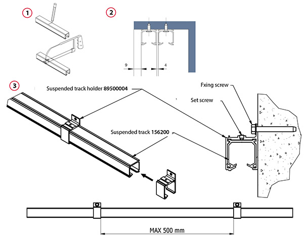
1. Cut the top track
Carefully measure the width of the opening at the top and reduce the length measured by about 2-3 mm. Measure off the required track length. Use a fine-toothed metal cutting saw to cut off the redundant part of the tracks.
Advice: The track to be installed should be about 50 mm longer than the width of the opening. This spare length will make it possible to avoid measurement errors and it is easy to trim.
2. Install the top track
Before fixing the top track, insert the rollers and the positioner into the track. Fix the top track with screws, offsetting its face by 9 mm.
Advice: Avoid applying excessive force when tightening screws to prevent track deformation. Use cheese-head screws for best result. The surface to which the track is fixed must not be curved.
Note: Before inserting the rollers, clean the inside of the suspended top track of any dirt that might accumulate during its installation.
3. Mount the top track to the wall
Insert the top suspended track holder 89500004 onto the suspended track. Fasten it against the track with an M5 set screw. The spacing of holders on the track must not be greater than 500mm to prevent track deformation during use. Fix the prepa-red track assembly to the wall with appropriate screws (the dimension of the fixing screw hole is 6.5mm). For aesthetic finish, a suspended track holder fascia 156230AS can be used or a furniture board fascia can be mounted on the holders.
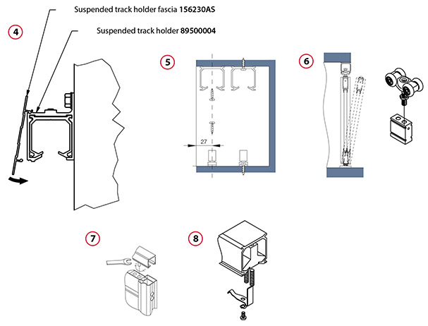
4. Install the suspended track holder fascia
Install the fascia after the suspended track with holders has been mounted to the wall.
The fascia fits only a suspended track with holders. Press the fascia onto the suspended track holders.
5. Install the guide
Determine a plane running vertically along the centre of the top rail (e.g. using a plumb line). Fix the guide to the floor.
6. Set the door in place
Put the door on the floor so that it engages the guide and stand it upright under the top rail. Screw the axles of the rollers 19-1 into the roller fixing blocks 19-2 until the leaf is lifted.
Advice:Exercise special care when installing the doors. This operation should be performed by two persons.
7. Adjust door position
Close the door and adjust the top roller axles so that the door is plumb when closed. By screwing in the axles, the door-to-floor height can be adjusted between 0 and 10 mm.
8. Fix the positioner
Having closed the door, move the positioner to a position in which the positioner tongue engages the top roller recess. Mark the position and adjust the door by fastening the positioner with the door open.
Advice: You can also use the positioner to determine the door position with the door open.
9. Fix the caps
Having installed and adjusted the door leaves, cover all installation holes by inserting the plugs 16000080 or by sticking the caps 16000090 or 16000085.
10. Fix the brush strips and buffer strips
To ensure good adhesion of the brush strips to the profiles, gently clean the profiles with alcohol or white spirit. Fix the strips, working your way from top to bottom. Cut off excess strip.
For the Niagara Windsor profiles, use a shorter 8 mm strip 81100019. For other profiles, use a longer 12 mm strip 81100020.
11. Fix the buffer strip clip
To fix the clip 099249 or 099249A, the door must first be installed and adjusted. After that operation, fix the buffer strip and then mount the clip. For easier and correct installation, we recommend that the door should be taken off the tracks.
Advice: For details of the buffer strip clip installation see separate instructions, “Technical information– fixing the buffer strip clip” available on our website in the section designated for Authorised Partners.
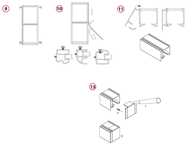
12. Install the suspended top track fascia
Cut the suspended top track fascia to the required length. Insert the fascia rib into the pocket on the upper edge of the track and press the lower side of the fascia so that it snaps into place on the top track.
13. Fix the suspended top track end cap
Suspended top tracks can be fitted with end caps if the tracks are shorter than the width of the opening or they are installed outside the opening fitted with sliding doors. Use a knife to cut off the redundant part of the cap on the desired side. Before finally fastening the track fixing screws, insert the cap tabs between the track and the ceiling. Then fasten the track fixing screws.
1. Install pivot sockets
Insert and fix the bottom pivot bracket with screws at a distance “y” from the wall, offsetting it inwards from the door face by “x”:
x = 20 mm for the Calgary Victoria Yukon Edmonton Hudson Quebec profiles
x = 27 mm for the Niagara Windsor profiles
y = 45 mm for the Calgary Victoria profiles
y = 39 mm for the Niagara Windsor profiles
y = 49 mm for the Quebec profiles
y = 54 mm for the Yukon Edmonton Hudson profiles
Advice: When fixing the pivot socket, set the screws at the centres of the oblong holes, which will enable you to adjust the position in both directions.
2. Set the door in place
Rest the door on the bottom pivot socket, putting it upright, and turn the top pivot socket. Then unscrew the bottom pivot pin, so that the door rises and fits tightly against the top pivot socket. Use a level to plumb the door and reposition the top pivot socket if necessary.
Advice: Exercise special care when setting the door in place. This operation should be performed by two persons.
3. Adjust the door
Door-to-floor clearance can be adjusted between 10 and 20 mm by screwing the pivot pins in or out.
4. Fix the magnetic latch
Having adjusted the door, close it, place the magnetic latch at the door leaf, mark the position and open the door. Fix the magnetic latch to the floor/ceiling/wall.
Note: The latch keeps the door in a stable position when closed.
5. Fix the caps
Having installed and adjusted the door leaves, cover all installation holes by inserting the plugs 16000080 or by sticking the caps 16000090 or 16000085.
6. Fix the brush strips and buffer strips
To ensure good adhesion of the brush strips to the profiles, gently clean the profiles with alcohol or white spirit. Fix the strips, working your way from top to bottom. Cut off excess strip.
7. Fix the buffer strip clip
To fix the clip 099249 or 099249A, the door must first be installed and adjusted. After that operation, fix the buffer strip and then mount the clip. For easier and correct installation, we recommend that the door should be taken off the tracks.
Advice: For details of the buffer strip clip installation see separate instructions, “Technical information– fixing the buffer strip clip” available on our website in the section designated for Authorised Partners.
8. Fix the decorative strips
Having adjusted the door leaf height, mark the levels where decorative strips are to be fixed to the door leaves. For each leaf, carefully measure the distance between the stiles. Then cut the decorative strips to the required lengths and fix do-uble-sided self-adhesive tape 16000005 (0.8 mm thick) to the strips. Remove the protective tape and, bending the strip slightly, put it between the stiles and press against the panel.
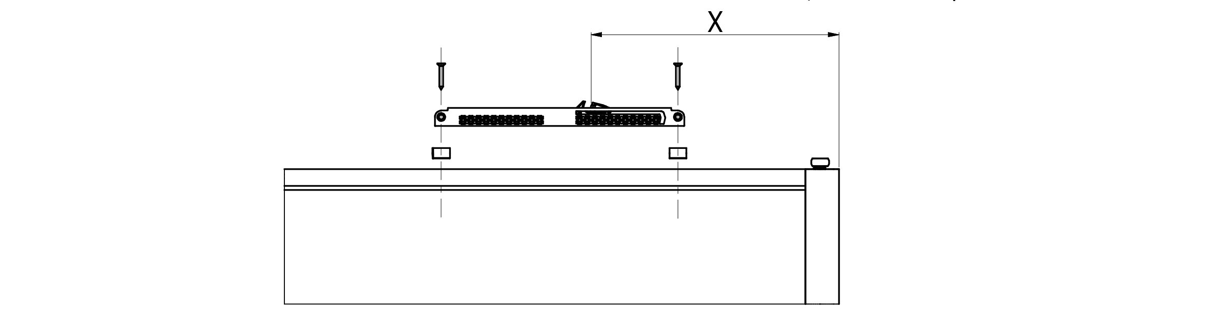
1. Installation of the universal soft closer in aluminium systems
Fasten the universal soft closer 09923X to the narrow rail by means of adapters and 3.5 x 23 screws (aluminium system soft closer accessories). Having fastened the closer, release the activator on the door, so it sits inthe position shown, then measure the distance “X” from the closing edge of the door.
 2. Installation of the soft closer trigger
Screw the activator plate into the track so that the bar is the same distance from the wall (“X”). First screw the main plate to the track, and then a single screw through the piece that rotates down to hold it up in position. This last single screw and the grub screw allows you to adjust the height of the bar if required.
Install the door and adjust the height of the door, so the soft close unit meets the activator plate.